Flamescapes: Simulating the Wildlandfire Urban Interface
Abstract
We present a physically based simulation framework for wildland–urban interface (WUI) fires that couples material-aware urban scenes with interactive combustion simulation. Motivated by the dominant WUI exposure pathways of direct flame contact, thermal radiation, and ember transport, our framework combines heterogeneous solid combustion, radiative heat transfer, ember transport, and explicit flame-front propagation. Urban scenes are generated from OpenStreetMap footprints using a procedural pipeline that represents buildings as combustible 3D structures composed of semantic atomic modules with material and fuel annotations. Building on a chemistry-based hybrid Eulerian–Lagrangian fire solver, we model material-dependent heating, conduction, pyrolysis, oxidation, fuel depletion, and ember generation. A hierarchical fuel graph couples semantic scene structure to the solver's solid fuel grid, enabling subcomponent-level mesh degradation. We demonstrate structure-to-structure ignition, radiative preheating, material-dependent burning, ember-driven spot fires, and validate the method through ablations and comparisons to real-world combustion experiments.
Video
Procedural Generation
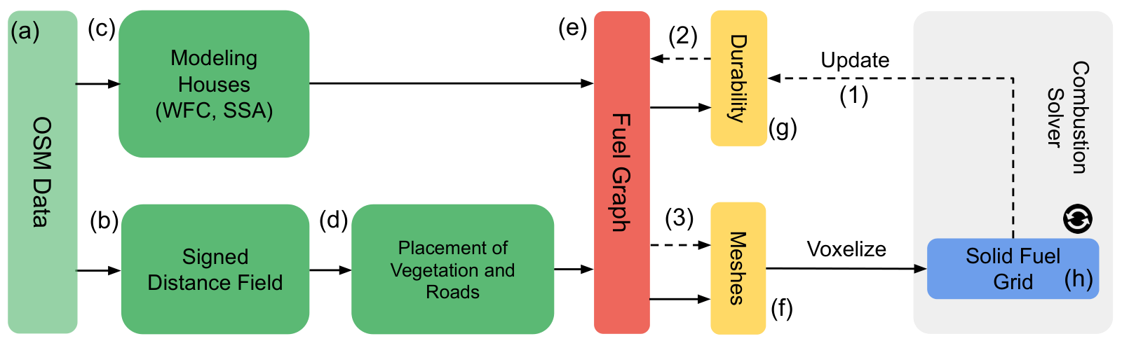
Overview of the modeling pipeline: at initialization (solid arrows) we use OSM building polygons and street center lines as input (a). We then compute an SDF (b) for placing street and vegetation assets into the scene (d) and procedurally generate 3D models of buildings with WFC and SSA algorithms (c). The scene is then hierarchically organized into a fuel graph (e), meshed (f) and then voxelized to obtain a solid fuel grid (h) for our combustion solver. To enable the element-wise combustion of buildings and vegetation during simulation (dashed arrows) we update the durability (g, 1) and the fuel graph (2) to identify combusted mesh elements (3).
Combustion Dynamics
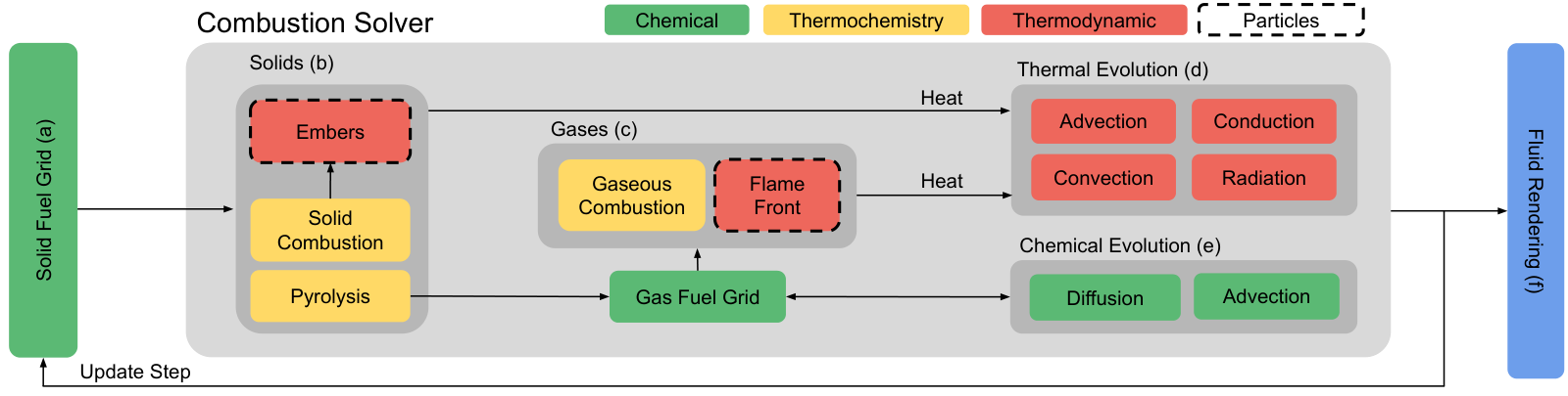
Overview of our solid-gas combustion solver. Solid fuels (b) are represented on a volumetric solid fuel grid (a) and evolve through pyrolysis and solid combustion, producing embers and gaseous fuels (c). Gases are represented as a gas fuel grid used for gaseous combustion and flame-front propagation. Thermal evolution (d) couples solids and gases via advection, conduction, convection, and radiation, while chemical evolution (e) is handled through advection and diffusion. Particle-based embers (b) provide a discrete transport mechanism across the domain, and the resulting fields are passed to the volumetric fluid renderer (f) for each update step.
Results
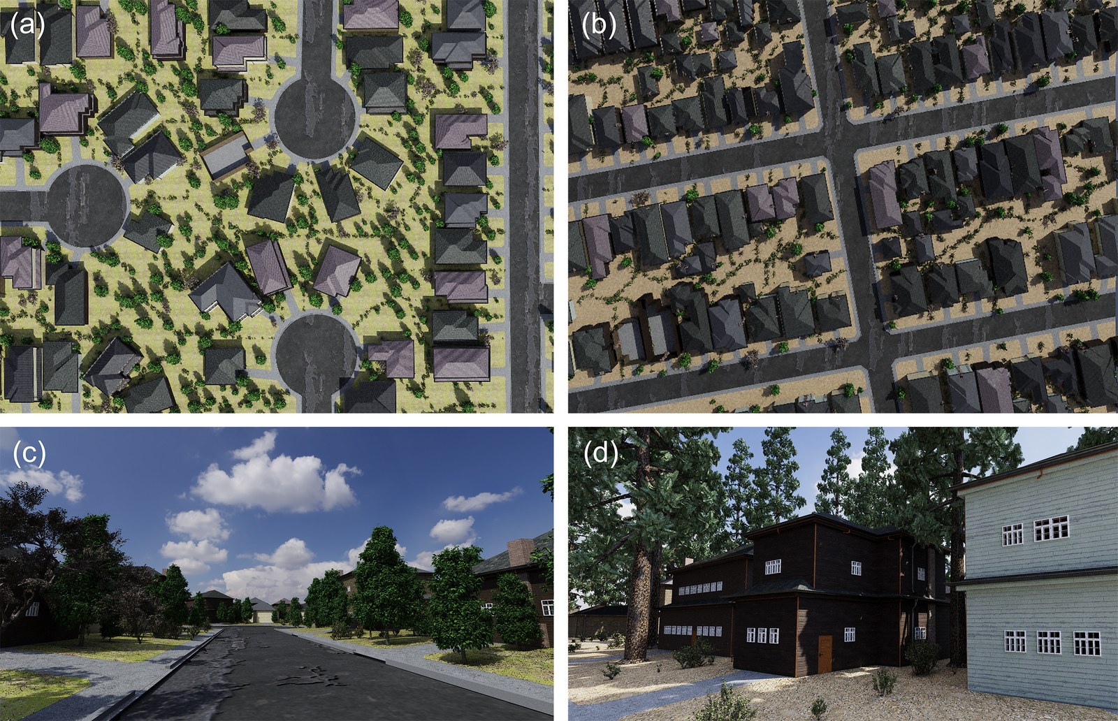
We procedurally model urban scenes from OSM data and based on a combustion-ready representation. With our framework we can generate urban scenes that resemble real geographic locations. Here we show top-down views (a, b) of urban scenes, and close-up renderings of houses (c, d).
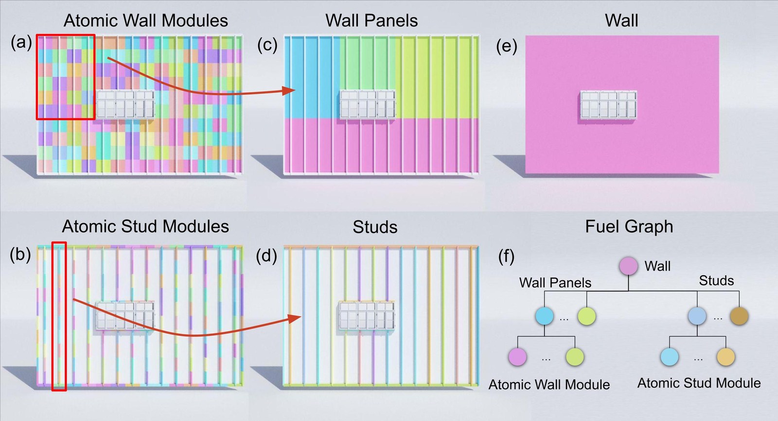
Organization of fuel: to efficiently represent complex urban environments for combustion dynamics, we use a hierarchical data structure for buildings that we refer to as fuel graph (f). At the lowest level, we use atomic modules (a, b), which represent the smallest resolvable units of combustible material and encode physical and thermochemical properties. The atomic modules are aggregated into higher-level wall panels and studs (c, d), corresponding to semantically meaningful architectural components. At the next highest level, these components are combined to form a complete wall (e) and at the highest level entire houses. A fuel graph enables physically meaningful aggregation of thermal properties and enables fire-related queries — such as heat transfer, ignition, and mass loss — to be evaluated at multiple semantic and spatial resolutions.
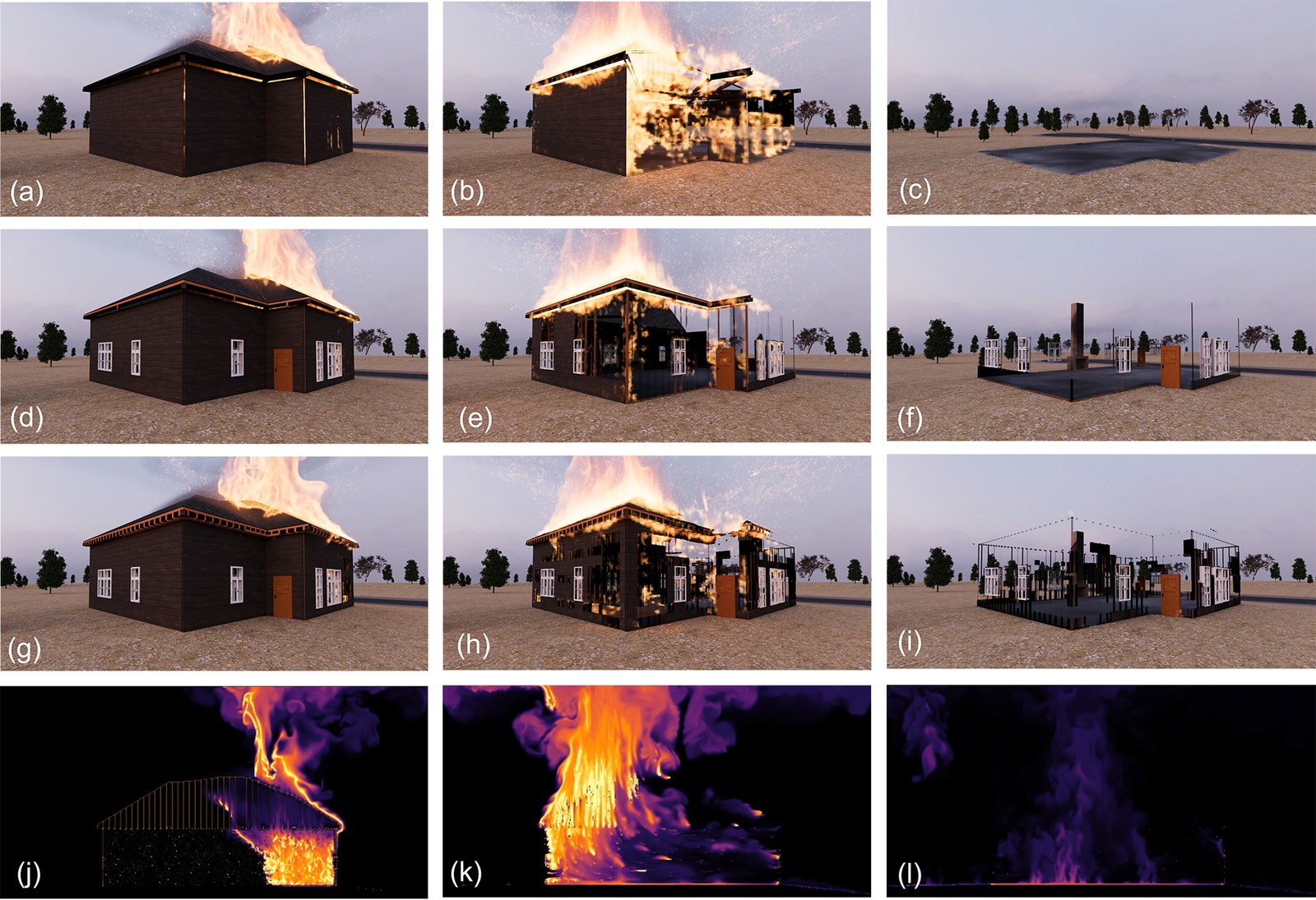
Visualization of fire propagation at different levels of the hierarchical fuel graph. At the coarsest building-level, it is only possible to remove large structural components, such as walls (a-c). The second row (d-f) visualizes the intermediate level consisting of wall panels and studs, revealing more detailed structural degradation. The third row (g-i) shows the finest geometric level, where individual atomic modules such as panels, doors, windows, and roof elements burn and disappear independently. The fourth row (j-l) shows a temperature slice through the building over the same sequence, illustrating how heat develops inside the structure and drives fuel depletion across the hierarchy.
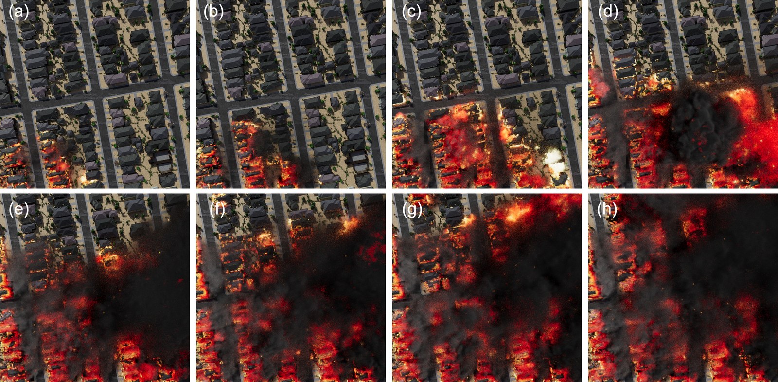
Temporal progression of an urban wildfire. The fire starts as a small cluster of burning houses (a-c) and subsequently develops to a larger fire (d, e) until it spreads across multiple blocks of houses (f-h).
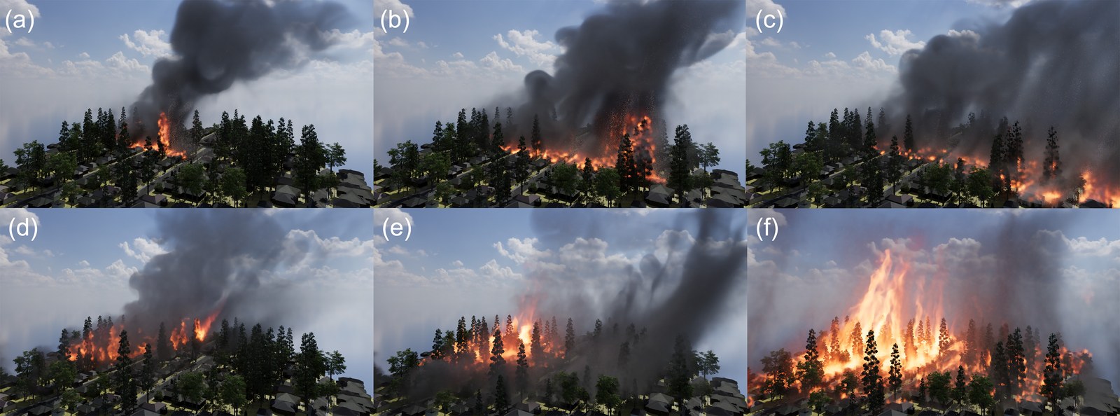
Effect of wind and biomass on urban wildfire progression. Under high wind an urban wildfire reaches a cluster of trees (a) and produces a large number of embers that are transported into the urban scene (b) and cause the wildfire to progress (c). Increased amounts of biomass results in a more vigorous fire (d) with stronger flames and increased heat release (e), which consequently leads to an intense urban wildfire (f).
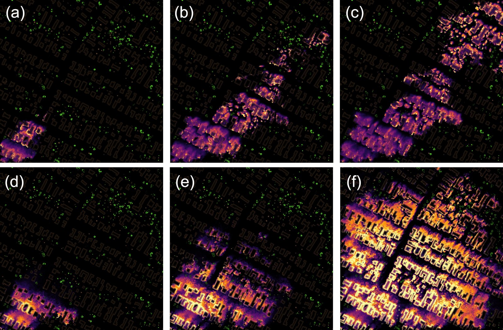
The same two scenes are shown as temperature (inferno color map), wood (brown color) and leaves (green color) from a top-down view. The higher wind scene develops a tongue-like fireline shape, whereas the low-wind but high-biomass scene has a more diffuse development and higher temperatures.
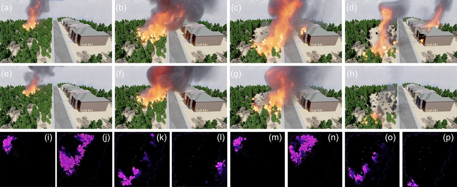
Temporal progression of urban wildfire simulations with (a-d) and without (e-h) ember transport under wind-heavy conditions. When embers are enabled, wind advects hot particles ahead of the flame front, leading to ignitions that can even overcome fuel breaks, such as streets (c, d). In the absence of embers, fire propagation remains more localized (g, h), highlighting the combined role of wind and ember transport in driving long-range ignition in urban wildfire scenarios. The top-down temperature maps for scenarios with (i-l) and without (m-p) embers provide a more detailed view of the fire propagation.
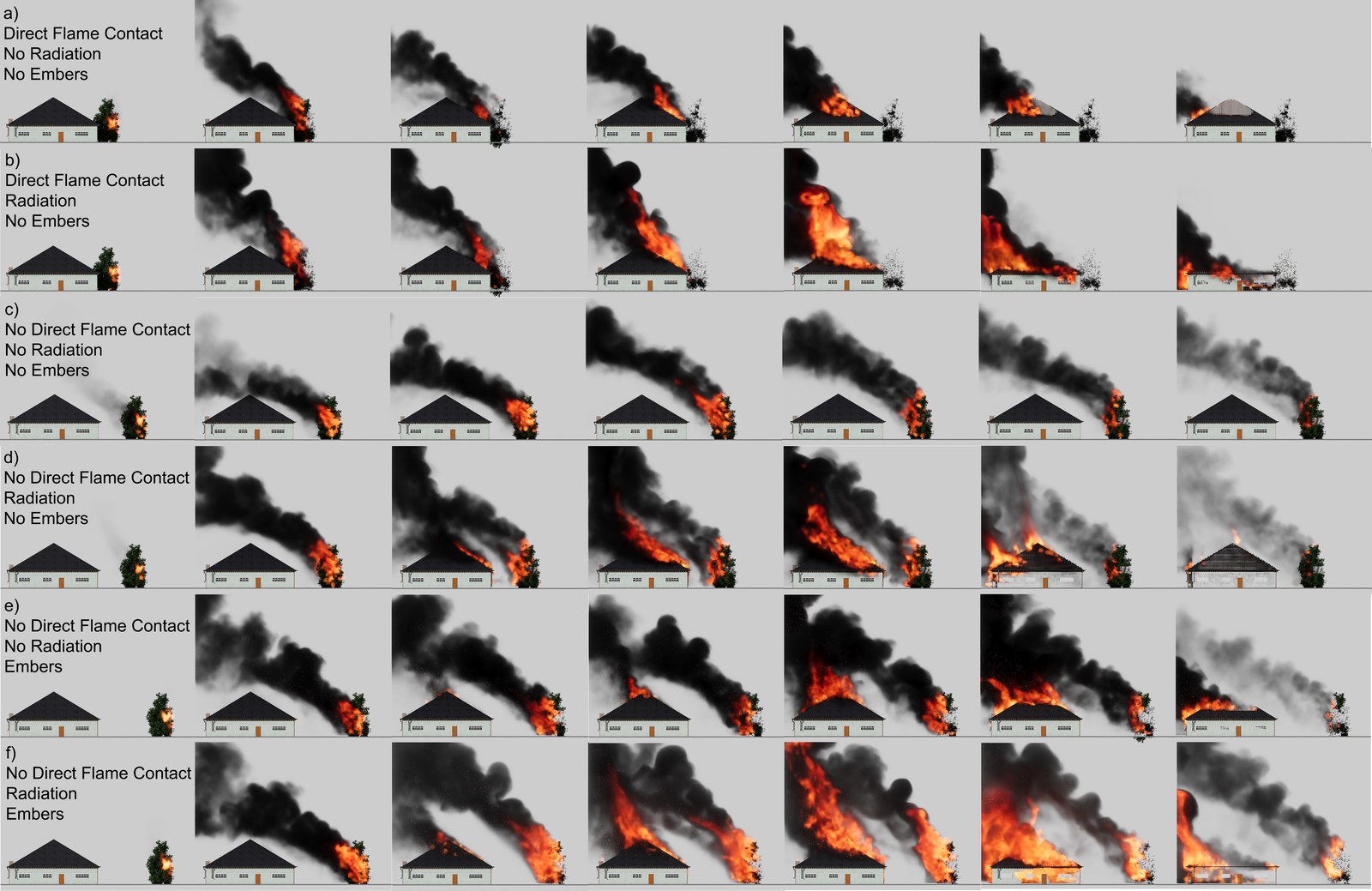
Ablation of WUI fire-spread pathways for a vegetation-to-structure ignition: each row shows a temporal sequence with a different combination of direct flame contact, radiative heat transfer, and ember transport enabled or disabled. With direct flame contact alone, fire spreads only when the flame reaches the building surface (a). Adding radiation increases heating of the facade and roof, leading to faster and more sustained structural ignition (b). Without direct flame contact and radiation, the fire remains localized to the vegetation and does not ignite the structure (c). Radiation alone can ignite the building across a gap between vegetation and structure (d), while embers introduce non-local spot ignitions on the roof (e). When all mechanisms are enabled, the combined effects produce the strongest and most persistent structure fire (f).
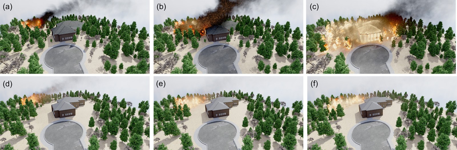
Comparison of two wildfire scenarios illustrating the effect of vegetation clearance on building ignition. In the dense vegetation case (a-c), the availability of continuous fuel enables fire to propagate to the structure, resulting in building ignition. In contrast, no vegetation around the structure (d-f) interrupts fuel continuity and prevents ignition. This demonstrates the protective effect of empty space around houses in WUI scenarios.
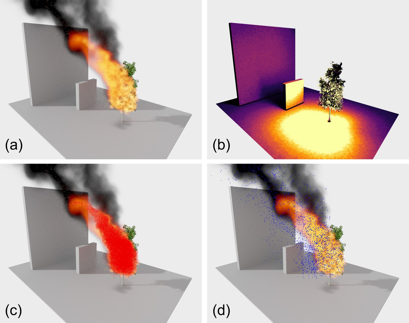
Visualizations of a burning tree (a), our ray-based radiation (b) as well as of particles for flame front propagation (c) and embers (d). Notably radiation is capable of transporting heat downwards and laterally but falls off quickly and is blocked by occluders, while the flame reaches primarily upwards. Flame front particles allow us to maintain a coherent flame shape which remains attached to the burning tree, even at low grid resolutions. Ember particles are more scattered and transport energy across larger distances and behind occluders.

Temporal progression of a simulated dry fir tree inspired by the NIST experiments. The sequence illustrates the combustion of a fir tree from ignition (a), flame growth (b, c), and peak heat release behavior (d) to the full combustion (e, f). Our simulation reproduces the characteristic fire growth dynamics and heat release trends of dry vegetation under controlled ignition conditions.
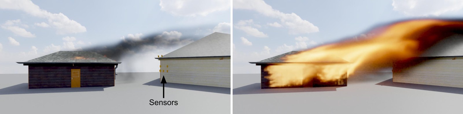
Wind-driven structure-to-structure fire-spread validation: we simulate a wood source structure with a downwind target structure and heat-flux sensors placed on the target facade. We then measure the radiative heat flux at multiple target sensors over time. The simulated fire plume is driven toward the target building, producing sustained radiative exposure and localized envelope heating without immediate full target ignition.
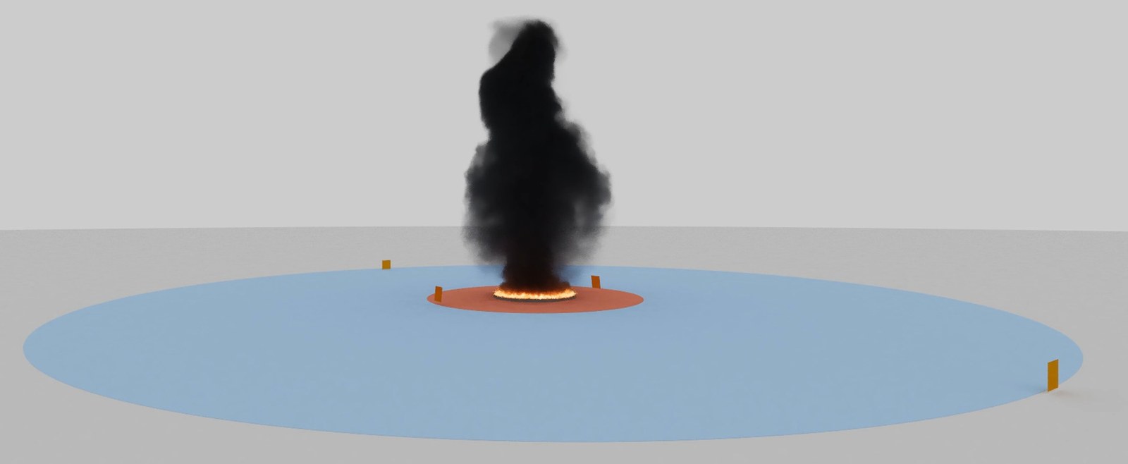
Radiative heat-flux validation using NISTIR 6546 Sample Problem 1. We simulated a 12 m pool fire with target probes placed at the NIST acceptable-separation distances (6 m, 10 m, 50 m, 55 m) for combustible structures and people. For combustible structures, the flux exceeds the NIST threshold of 31.5 kW/m² at 6 m but remains below it at 10 m. For people, the flux exceeds the exposure threshold of 1.4 kW/m² at 50 m but remains below it at 55 m. These results reproduce the expected separation-distance behavior of the NIST benchmark.
BibTeX
Coming soon.